The first thing that I believe stopped it from happening on a large scale is the availability of the right technology. While Tesla was able to harness this energy for himself at his lab in Colorado Springs, he had a large area to develop the correct machinery and stuff to collect this radiant energy. (By the way, the term radiant energy is the term Tesla gave it and is the wrong name for the energy he was collecting.) Most homes don't have the kind of room his laboratory had (before the Marines blew it up) therefore would not have the ability to store the devices necessary as the technology of the time meant the devices were quite large and bulky. Today, on the other hand, we live in an age of miniaturization. The large capacitors and such of Tesla's day are now scaled down to the size of a fingernail. This makes harnessing this energy much more practical today. Additionally, with today's metallurgy technology, we can produce much purer metals and other materials than Tesla's contemporary's could.
So let's look at how we can begin to harness this "radiant energy" that Tesla discovered. In order to do this, we must first figure out what exactly it was that Tesla was really harnessing. What is really going on? Based on my research into the theories and inventions of Tesla, I believe the energy source he was referring to is simply electromagnetic waves. We know the Earth is a giant magnet with a north pole and a south pole. And usually, the magnetic force travels in an arc around the planet from the north to the south poles. When radiation from the sun comes into contact with this we can sometimes see what is known as the Auroras. I believe this is what Tesla was learning to "harvest" in his experiments.
To prove or disprove this theory, let us experiment with some of Tesla's ideas and some modern technology to see what we can develop.
First, we need a way to harvest the energy. To do this, I will build a small scale antenna using 20 feet (6.1 meters) of 1/4" refrigeration tubing and coiling it so it has approximately 1/2" to 1" of gap between each turn. This will be placed on top of a short pole measuring 5'-10" (1.78 meters). This pole with its copper coil on top will have a 14 gauge wire attached to it leading down to some mag wire (30) which will attach to a circuit which will be described later. The circuit will also be attached to a ground wire which will be attached to a 14 gauge wire thrust 6" (.15 meters) into the ground. The antenna will be held into the air by my nephew Kevin as high as the wiring and his arms will allow. Total altitude should be around 12 feet (3.66 meters).
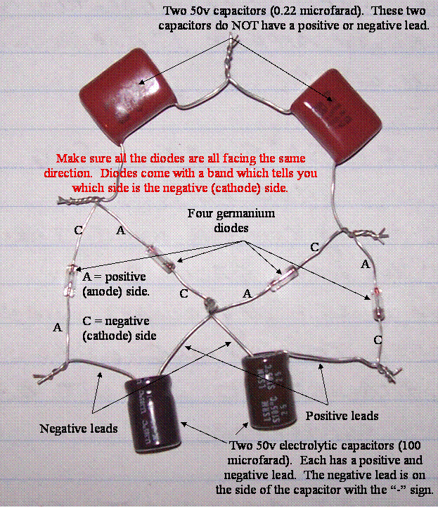
Here is the circuit (photos and video included with this post will show you how it is put together). Using two ceramic capacitors rated at 50v .22 microfarad (yes that is POINT 22 microfarad), two electrolytic capacitors rated at 50v 100 microfarads and four germanium diodes, we are going to create a circuit which will allow us to measure the voltage collected by the antenna, if any.
And here are a couple of pictures showing the antenna:


We conducted the experiment on October 30, 2010. The purpose of this experiment is merely a proof of concept. All we are interested in doing with this experiment is determining whether or not the theory has any merit and, if so, is it worth exploring further.
The temperature on October 30, 2010 in Salem, Oregon was rain and fog with the temperature at 50 degrees Fahrenheit at 11:00 a.m.
I took a primary reading after building the device. I was shocked to see that I had a 0.04v charge stored. It immediately dissipated. I took the reading several times before connecting the circuit to the antenna and found this same charge stored in the device. Interesting. Maybe something that needs to be explored later.
We placed a 14 gauge wire six inches into the ground and attached mag wire to it. The other end of the mag wire we attached to the circuit between the two electrolytic capacitors. We attached a 14 gauge wire to the copper coil which is the top of the antenna. At the end of that wire we attached more mag wire. The other end of that piece of mag wire we attached between the other two capacitors completing our circuit. Kevin then lifted the antenna to a height of approximately 12 feet. I took a reading with my digital voltmeter. We had a current of 1.8v DC. It rose to 2.4v DC where it leveled out.
This is enough to prove the concept. It is, indeed, possible to harness Tesla's "radiant energy". Unfortunately, the levels of energy are very small and the amperage is smaller still. But, that doesn't mean that when we ramp up the tests we won't get better results. Before we do that, though, we need to conduct a few more small scale experiments. Once we have done this, we can move on to larger scale.
Overall, the first test was a success! There is sufficient evidence to suggest that the energy can be harvested in quantities large enough to perform meaningful work. This experiment will continue.
Novermber 1, 2010. Need to make a correction in the original data results. I did not pay attention to where I had placed my meter setting. It was set at 200m in the DCV section. Therefore my results were actually 2.4 mV. Sorry for this confusion. Please see the next video and post addition for some interesting news on the next phase of the experiment.
Hi, I am Ravi From India. i m student of engineering i m trying to build circuit that you have explain here . but its not working . I have used same component that 224 ceramic capacitor, 100uF electrolytic capacitor , 1N31 germanium diode. connected all component as shown in fig. and antenna that i m using is GSM Dual band antenna . and at ouput DC i have connected LED.
ReplyDelete1. How much time it require to charge capacitor.
2. Any problem with component that i used.
3. Any Problem with antennna i m using.
Please do reply me if possible on
raviasati@gmail.com
No news experience? There they have another site?
DeleteHi, I've the same problem that ravi, can you upload an image with the detailed connection of the antenna to the circuit? do you have more experiences with this?
ReplyDeleteI'm using a 100uF 16v caps and other question I have is.. Can you connect more diodes to use as an alternative to the antenna?
Thanks, I'm not an experienced guy in electronic field, please my apologies if some of my question are trivial.
This comment has been removed by the author.
ReplyDeletehttp://www.free-energy-info.com/Chapt7.html.......The TREC
ReplyDeleteIf you release something,please write me to.I don't know english,i use google translate.My usual email adresse is pgeorge88@yahoo.com.
ReplyDeleteIn the TREC,tray to respect all is write there.Success!!
try using the disc antenna instead of the spiral antenna. It will get you collect more torsion energy.
ReplyDeletewhat it the input impedance of RF to DC circuit
Deletewhat it the input impedance of RF to DC circuit
ReplyDeletegod only knows :P
DeleteRezonančná frekvencia. Tu ing. SLOVAKIA
Deletehonestly, this article is total BS. No video because of some stupid excuse? You can figure out free energy, but you cannot figure out how to get video online in 2010? I call this as misinformation... and it exists to waste people's time on this crappy experiment.
ReplyDeletei just experiment with this it really works, you need to wire correctly and attach the antenna to the top between the capacitors and ground the wire between the catalytic capacitors, and experimenting moor, this is just the beginning and a starting circuit TBH it can be improved in many ways
ReplyDeletehi dear its very first-class and very helpful submit for those who are new and thinking to begin a weblog site.Your posts are very helpful and creative click on right here and see about inverters
ReplyDeleteI used 1n4148 diodes, i got around 1,5 volts.
ReplyDeleteFisbola, merupakan situs judi slot online terpercaya no
ReplyDeleteFisbola, merupakan situs judi slot online terpercaya no 메리트카지노 1 di Indonesia. Untuk karena situs judi online terbaik, 샌즈카지노 slot88, bola dan 메리트 카지노 poker.
Hook it up to a speaker or scope. OMG! it's RF and a shitty antenna, LOL! Learn some basic science or stay stupid, it's your choice.
ReplyDeleteHere you go chuckleheads https://www.youtube.com/watch?v=hh7xgTu1jYs
ReplyDeleteI tried this experiment. It charges but in millivolts. It can not light a LED. Set your Multimeter at lower voltage you will see the charging effect.
ReplyDeleteGracias por el aporte, para conseguir que sea un generador potente se debe de crear varios módulos para poder arrancar una bombilla de 24v en la cual está unido a un ladron de Julios.
ReplyDeleteDeben de existir dos puestas a Tierra que esta a 100cm y la antena quizás a 10Metros de altura los Diodos 1N34, (otros 1N60) Cp100Microfaradios 50v. Cp NF 222.
Cool and that i have a super offer: How Much Home Renovation Can I Afford home renovation construction
ReplyDelete